Feed and flow control
A balance vessel or feed arrangement supplies the product to a suitable pump. Flow is a safety-relevant input because it influences residence time, pressure drop and heat transfer.
Technology / process path
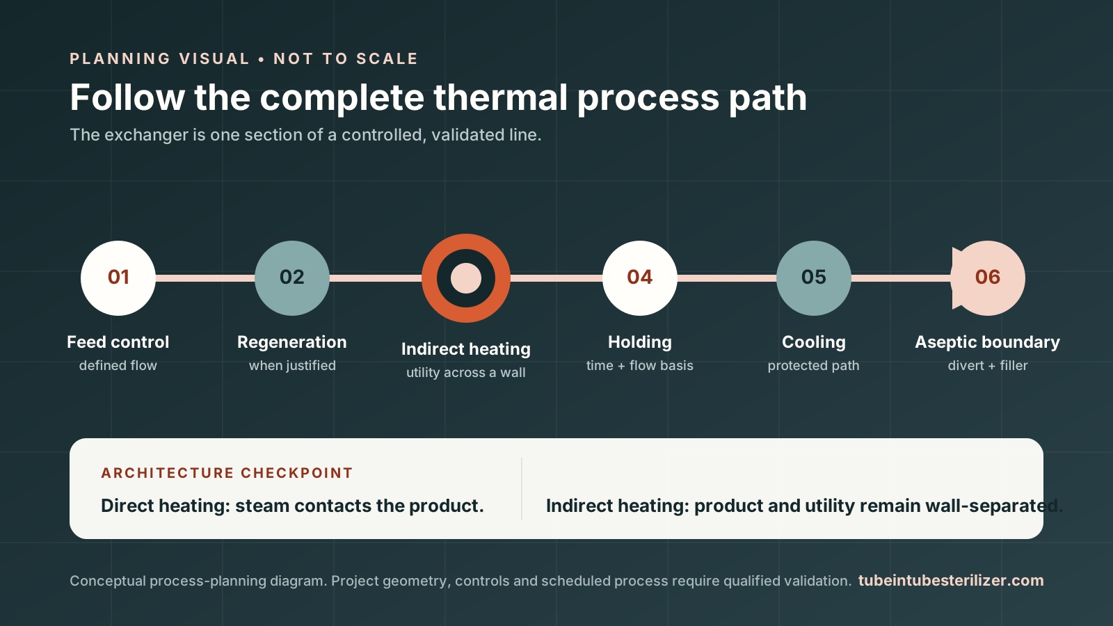
A tube-in-tube heat exchanger is one part of a continuous thermal process. The engineering boundary includes flow control, heating, the holding section, cooling, monitoring, diversion and every product-contact surface downstream.
01 / The thermal path
A balance vessel or feed arrangement supplies the product to a suitable pump. Flow is a safety-relevant input because it influences residence time, pressure drop and heat transfer.
Where product-to-product regeneration is used, incoming product can recover heat from processed product. Pressure relationships must be part of the hygienic risk assessment.
Heating media and product remain separated by the tube wall. Tube geometry, velocity, product properties and fouling determine the real heat-transfer behaviour.
Length, internal geometry and verified flow determine residence time. The fastest product element—not the average alone—must meet the scheduled process.
Cooling or regeneration brings the product to the condition required by the aseptic tank or filler while maintaining the post-process hygienic boundary.
If validated limits are not met, suspect product must not proceed as acceptable output. Temperature, flow, pressure, valve state and alarms need a defined control philosophy.
Compare direct steam and indirect UHT heating boundaries
Review holding-tube residence time and fastest-path evidence
02 / Inside the exchanger
Tube-in-tube normally refers to concentric double-tube or annular arrangements. Product may flow through an inner tube or annular passage while utility media flows in the adjacent passage. Multitube, monotube, coiled and other tubular exchangers are related architectures, not automatic synonyms. Supplier terminology varies, so confirm the actual cross-section, product passage and service-media path.
Is every tubular heat exchanger tube-in-tube? No. Compare the physical flow paths and process duty instead of relying on the category label.
Compare exchanger architecturesConceptual cross-section — not a Site34 product drawing.
Product side
Equipment side
Critical distinction
The scheduled process belongs to the exact product, flow, holding geometry, sterile zone, package and operating method. A qualified process authority should establish the applicable thermal process where required.
Translate process into equipment
Begin with viscosity behaviour, particulate profile, required flow, thermal target and the downstream line.
Request a quotation