CONTINUOUS THERMAL PROCESSING · PURÉE / PASTE / CONCENTRATEsales@tubeintubesterilizer.com

Integration / hygienic boundary

CIP, SIP and aseptic filler integration for tube-in-tube sterilizers.

Cooling sections, valves, pumps, instruments, tanks, filler connections and packaging all influence the integrity of an aseptic process. Define the complete path before assigning equipment scope.

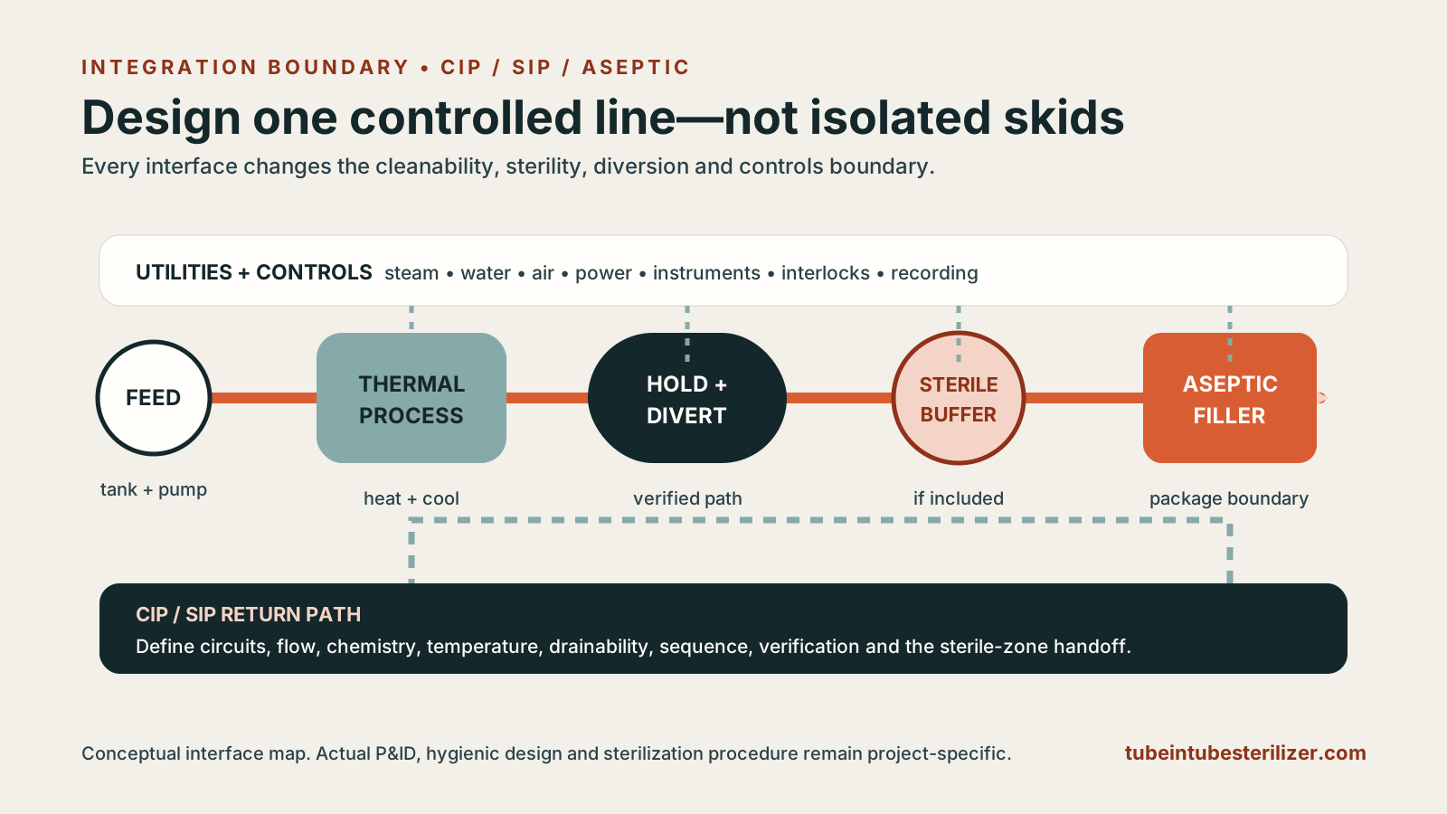
Conceptual food-process line showing feed, thermal processing, holding and diversion, sterile buffer, aseptic filling, utilities, CIP and SIP interfaces
Process illustration. The hygienic and sterile boundary spans equipment, controls, utilities, cleaning circuits and the downstream filler interface.
  1. UpstreamFeed tank + pump
  2. ThermalHeat + hold + cool
  3. ProtectionDivert + monitor
  4. AsepticTank or filler
CIP

Cleaning in place

Remove soil from the actual product path.

Cleaning performance depends on residue chemistry, hydraulic coverage, time, temperature, chemical concentration and return conditions. “CIP-ready” is not a validated cleaning recipe.

  • Defined circuit and flow direction
  • Cleaning-station capacity
  • Chemical compatibility
  • Rinse endpoint and verification
SIP

Sterilization in place

Prepare the post-process zone before product.

Pre-sterilization or SIP establishes the required hygienic condition through the holding section and downstream path. Its medium, temperature, time, condensate removal and boundary must be engineered and validated.

  • Defined sterile zone
  • Validated exposure
  • Barrier and valve states
  • Controlled transition to production

Cleanability proof

Validate the real soil, circuit and endpoint—not the label “CIP-ready”

Hygienic design review identifies avoidable traps, but it does not by itself prove that the assembled process line reaches its cleaning objective. CIP and SIP also answer different questions: remove soil first, then establish the required pre-production hygienic or sterile condition for the defined downstream boundary.

Worst credible soil

Identify the formulation, deposit, campaign length, temperature history and idle condition most likely to challenge cleaning.

Complete circuit

Map every product-contact branch, valve position, bypass, instrument, return path, drain point and equipment interface.

Controlled cycle

Define flow or coverage, chemical identity and concentration, temperature, time, sequence, rinse and the instruments that record them.

Objective endpoint

Select risk-appropriate visual, chemical, hygienic or microbiological evidence and state sampling locations and acceptance criteria.

Failure response

Predetermine what happens after an interrupted, out-of-limit or failed cycle, including product disposition and repeat-cleaning logic.

Change control

Reassess product, recipe, circuit, chemical, software, valve, instrument or downstream-equipment changes that can alter the validated boundary.

Aseptic filler interface

Eight interface questions to close before design freeze

01

Connection

Hygienic connection type, size, orientation and service access.

02

Barrier

Sterile steam, sterile water or other validated barrier arrangement.

03

Pressure

Required backpressure and safe pressure relationship across the line.

04

Capacity

Filler rate, turndown, buffer strategy and start/stop behaviour.

05

Handshake

Ready, run, hold, fault, divert and safe-stop signals.

06

Cleaning

Where CIP circuits meet and which machine owns each valve sequence.

07

Sterilization

Boundary, medium, sequence, acceptance and restart after interruption.

08

Records

Critical values, alarm history, batch identity and operator actions.

Control philosophy

Define what happens outside the acceptable process envelope.

Temperature below the validated limit

Prevent suspect product from entering the acceptable aseptic stream. Define diversion, hold, recirculation or disposal logic with the process authority and line owner.

Flow above the validated limit

Residence time may be reduced. Flow measurement, control and response must be part of the scheduled process boundary where applicable.

Pressure relationship is lost

Where regeneration or sterile interfaces rely on differential pressure, the control system must identify and respond to the unsafe state.

Filler or downstream equipment stops

Agree the upstream response, safe hold time, recirculation constraints, restart sanitation and product-disposition rules.

Evidence boundary

Component cleanability and complete-line validation are not the same claim

These sources support hygienic design, CIP planning and aseptic-system review within their stated scopes. They do not certify Site34 equipment or supply a universal cleaning cycle.

Hygienic and regulatory references

  1. 3-A — Installation and CIP of processing equipment and hygienic pipelinesIndustry-standard context for installation and CIP boundary planning.
  2. EHEDG — Cleanability and CIP testing FAQExplains the distinction between design review, defined component scope and practical cleanability testing.
  3. U.S. FDA — Aseptic processing inspection guideSystem-boundary, pre-sterilization, downstream sterile-zone and control context for U.S. low-acid aseptic processing.

Interface review

Bring the upstream and downstream equipment into the same conversation.

Include tank, pump, CIP station, utilities, aseptic filler and control details in the first process brief.

Request a quotation
Discuss your equipment