Fruit purée and pulp
Fibre, pulp fraction, viscosity curve and particle integrity influence passage size, pump choice and cleaning access.
View purée applicationCONTINUOUS STERILIZATION EQUIPMENT
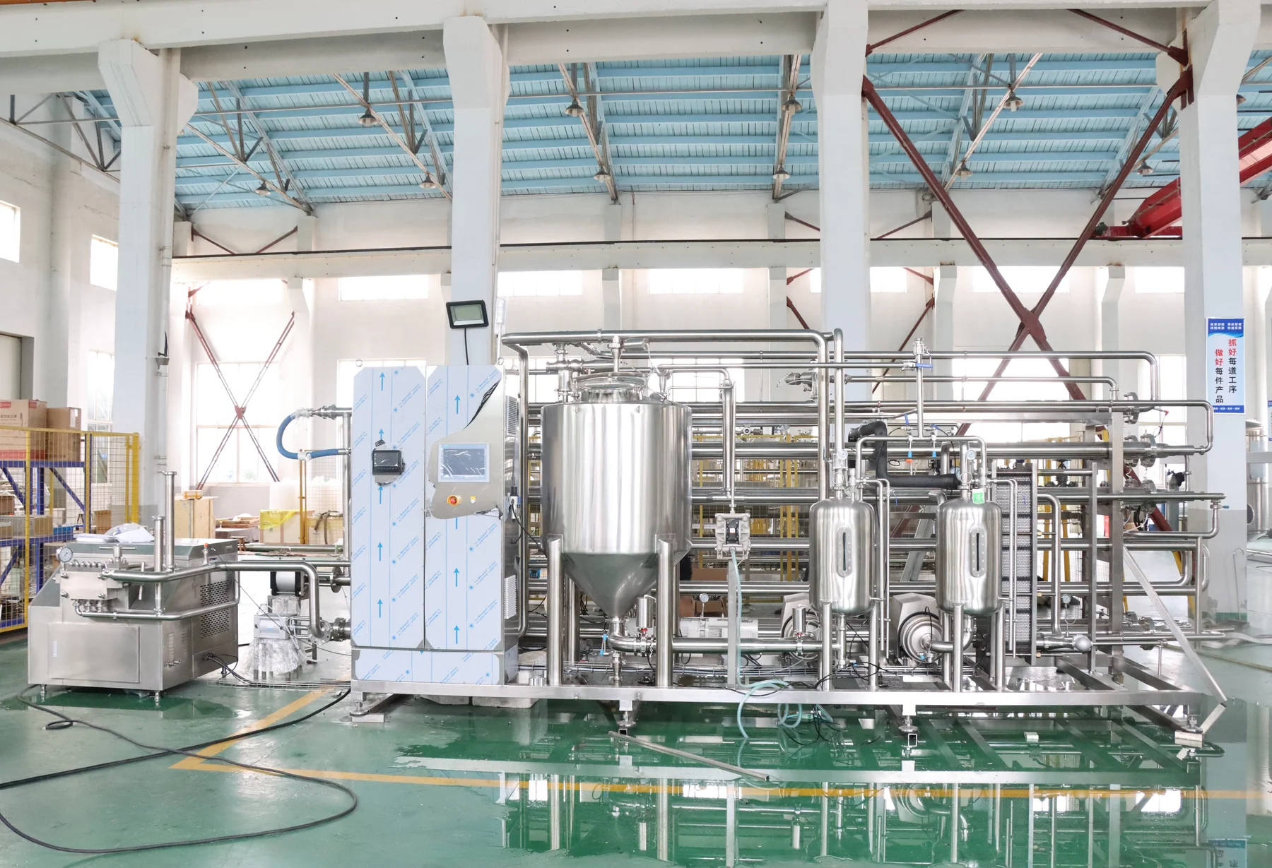
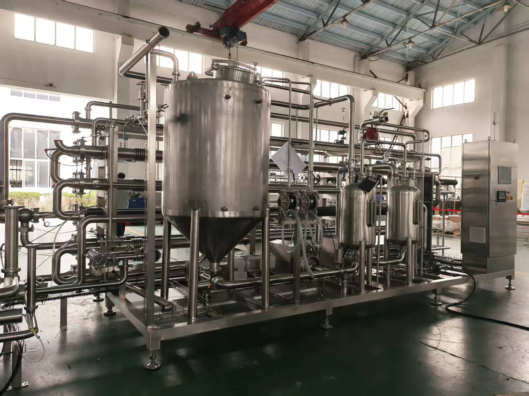
A continuous system for pumpable fruit purée, concentrate and sauce duties. Product is fed through an indirect heating section, held for the specified process, cooled, and transferred toward the agreed aseptic boundary. Tube geometry, pump, instrumentation and downstream connection are selected together for the actual product.
01 / System assembly
The scope is a connected machine package. The final offer identifies which modules arrive with the sterilizer and which connections belong to existing plant equipment.
On a narrow screen, scroll the table to compare each assembly and its interface.
| Assembly | What it does | Design interface |
|---|---|---|
| Product feed and pump | Moves purée or concentrate at controlled flow into the heating path. | Viscosity, particle passage, inlet pressure and minimum flow set the pump duty. |
| Tube-in-tube heating | Transfers heat indirectly across metal surfaces while keeping product and utility media separate. | Tube geometry, pressure drop, fouling access and service-medium condition are project-specific. |
| Holding assembly | Provides the flow path for the established minimum residence time. | Volume, flow measurement, worst-case flow and the validated thermal schedule must agree. |
| Cooling and outlet | Reduces product temperature for the next closed handling step. | The aseptic tank or filler connection, sterile barrier and transfer pressure are defined at the interface. |
| Controls and records | Monitors process temperature, flow and defined transitions. | Setpoints, alarms, diversion logic and record retention belong in the agreed control specification. |
02 / Catalogue reference
The 2026 equipment catalogue lists the following reference options for this tube-in-tube sterilizer family. A quotation identifies the actual supplied materials, utilities and control functions; the product-specific thermal schedule is validated separately.
On a narrow screen, scroll the table to inspect all reference values.
| Item | 2026 catalogue reference | Project decision |
|---|---|---|
| Processing capacity | Configured for the project | State product, flow and turndown in the quotation. |
| Temperature capability | 72–150 °C adjustable | Set the actual treatment temperature from the product's validated process. |
| Holding-time range | 15–120 seconds adjustable | Confirm holding path and minimum flow against the process schedule. |
| Heating medium | Hot water or steam | Confirm utility condition and heat-transfer arrangement. |
| Cooling medium | Cold water or ice water | Confirm required outlet condition and available utility. |
| Contact material | SUS304 or SUS316L | Select material to suit the product and cleaning chemistry. |
| Control system | PLC automatic control | Define recorded signals, alarms and line handshakes. |
03 / Operating path
These functions make one continuous system. Product-specific thermal validation determines the actual operating values, not a universal catalogue maximum.
Confirm inlet product consistency and measurable flow before treatment.
Match annular product passage and heat-transfer area to viscosity, solids and fouling behaviour.
Link the scheduled minimum time to measured flow, temperature and the holding-path geometry.
Cool within the closed product path to the downstream handling condition.
Connect to a compatible tank or filler through the specified sterile boundary.
04 / Product fit
Fibre, pulp fraction, viscosity curve and particle integrity influence passage size, pump choice and cleaning access.
View purée applicationSolids, shear sensitivity and fouling tendency determine whether a tube-in-tube arrangement is suitable for the required duty.
View paste applicationThe sterilizer, tank and filler must agree on transfer temperature, pressure, pre-sterilization state and control handshakes.
Inspect integration boundary05 / Cleaning and service
The product path, valves, pumps and connections are reviewed as one cleaning circuit. Chemical recipe, flow and verification method depend on the residue and plant utilities.
Any SIP or hot-water sequence, sterile-air boundary and changeover to production must match the supplied valves and downstream system.
Include accessible seals, instruments, joints and tube sections in maintenance planning. The final equipment drawing establishes exact service clearances.
Temperature, flow, alarms and state transitions support process review. The product's validated schedule and local requirements define the record set.