CONTINUOUS THERMAL PROCESSING · PURÉE / PASTE / CONCENTRATEsales@tubeintubesterilizer.com

Technology comparison / process fit

Tube-in-tube or plate heat exchanger?

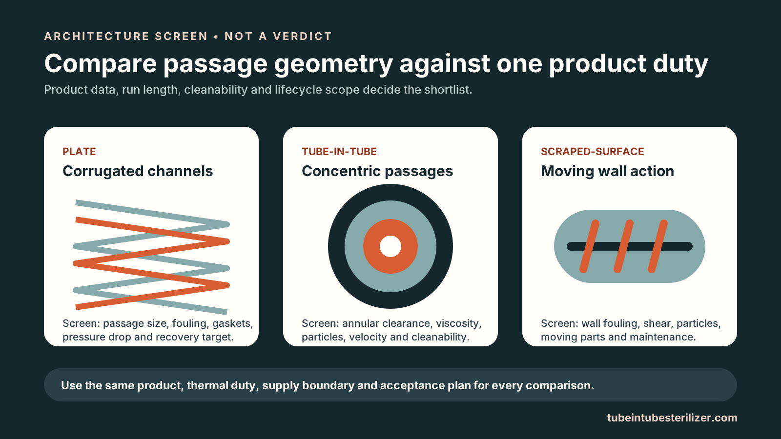
Neither architecture is universally better. Plate systems are often evaluated for pumpable homogeneous liquids and compact heat-transfer duties; tube-in-tube arrangements are often evaluated when viscosity, fibres or particles make passage geometry a dominant constraint. The final choice still depends on the measured product, process duty, run length, cleanability and complete line economics.

Conceptual comparison of plate, tube-in-tube and scraped-surface heat exchanger passage architectures
Process illustration. Architecture should be compared against the same product, thermal duty, supply boundary and acceptance plan.

Concentric tubular path

When tube-in-tube enters the shortlist

A relatively open, defined product passage may be useful when the product is viscous, contains fibres or particulates, or needs gentler passage geometry. That does not prove fit: pressure drop, heat transfer, holding behaviour, pump selection and fouling still need project evidence.

  • Rheology changes across temperature and shear
  • Particle dimensions and concentration affect clearance
  • Product integrity matters after pumping and heating
  • Run length and CIP recovery affect the operating case

Plate channel path

When plate remains a serious candidate

Plate exchangers may offer a compact indirect heat-transfer surface and strong regeneration opportunities for products that can move reliably through the selected channels. Channel spacing, gaskets, allowable pressure, fouling, inspection and cleaning remain part of the decision.

  • Homogeneous or lower-viscosity flow may suit plate channels
  • Approach temperature and heat recovery can shape economics
  • Product and gasket compatibility must be confirmed
  • Fouling and cleaning frequency can change lifetime cost

Side-by-side screening

Compare the duty, not the brochure category

Questions to resolve when comparing tube-in-tube and plate heat exchangers for food thermal processing
Decision variableTube-in-tube questionPlate questionEvidence to collect
ViscosityCan the selected passage meet velocity and pressure-drop limits?Can the product move consistently through the channel pattern?Rheology curve at process temperature and shear
Particles and fibresDo tube, pump and filler clear the complete particle profile?Do channel gaps and ports protect flow and product integrity?Three-axis distribution, concentration, hardness and fibre length
Thermal dutyWhat area, passes and utility conditions meet the process basis?What plate arrangement and approach temperature meet the same basis?Inlet, target, hold, outlet and heat-property data
FoulingWhat velocity and circuit design support the required run length?How quickly do channels lose performance under the same product?Representative run or fouling evidence
CleaningCan the full tubular circuit achieve the validated CIP conditions?Can every channel and gasket boundary achieve them?CIP flow, chemicals, time, temperature and verification
Pressure and recoveryHow do pressure drop, regeneration and pump duty affect the line?How do pressure rating and regeneration arrangement affect the line?Hydraulic model, utility balance and safe pressure relationships
MaintenanceHow are tubes, seals, welds and product passages inspected?How are plates, gaskets, ports and frame condition inspected?Service access, spares plan and inspection procedure
Total project scopeAre pumps, holding, cooling, diversion, controls, CIP/SIP and downstream interfaces compared on the same boundary?Matched supply list, acceptance plan and lifecycle-cost basis

Name the architecture

“Tubular” is a family, not one cross-section.

Tube-in-tube normally means concentric double-tube or annular product/service passages. Multitube, monotube, coiled and scraped-surface designs solve different product and mechanical problems. A supplier may group several of them under “tubular,” so request a cross-section and identify exactly where product and utility flow.

Likewise, “plate” can include different plate patterns and frame arrangements. A fair comparison fixes the same product, throughput, thermal target, outlet condition, run length and acceptance criteria before judging area, utilities, maintenance or price.

Compare tube-in-tube with scraped-surface heat transfer

Decision sequence

Six checks before choosing an exchanger

01 / Characterize

Measure rheology, density, heat properties, particles, fibres, fouling and quality constraints under relevant conditions.

02 / Fix the duty

Define inlet, scheduled thermal process where applicable, holding basis, outlet condition, nominal flow and turndown.

03 / Model the path

Compare heat transfer, pressure drop, residence-time implications and pump duty for the actual product passage.

04 / Test uncertainty

Use representative product and agreed measurements when rheology, fouling, particle integrity or run length cannot be predicted responsibly.

05 / Close hygiene

Compare drainability, inspection, CIP/SIP boundary, materials, seals, surface and weld documentation on the same basis.

06 / Match scope

Include recovery, controls, diversion, downstream equipment, FAT/SAT, commissioning, spares and acceptance before comparing price.

≠

No universal winner

A product label cannot select the exchanger.

A viscous sauce, for example, can behave very differently as formulation, temperature, shear and particles change. Treat architecture selection as an evidence-backed engineering decision, not a category rule.

Prepare the comparison inputs

Compare on one basis

Bring product data and a matched supply boundary.

The RFQ brief records the unknowns so a future technical review can compare architectures without inventing limits.

Request a quotation
Discuss your equipment